FEATURES OF ASK BALL BUSHES
■Low Friction
ASK Ball Bushes work on the rolling friction principle which keeps surface contact with the shaft and thus friction losses to a minimum. There would be no appreciable increase in friction despite any speed change or any increase in load within ASK specifications. This assures continuous smooth travel of the balls.
■High Precision
Low friction running of Ball Bushes affords minimum wear in diameter of balls and high precision guiding over a long period of time. Our perfect quality control system ensures the high quality of the products.
■Low Noise
The steel balls make a rolling motion on the precisely ground raceway surface, which ensures smooth operation of the bushes with minimum noise.
■Wide Variety of Types
A variety of types such as standard single type, double type, flanged single type, flanged double type etc. are available to meet various needs of market. Among ASK Ball Bushes you can choose the bushes most suitable to your requirements.
CONSTRUCTION
The steel balls circulate on the ball track within the retainer while making rolling contact with the outer circumference of the shaft, so that the bush runs with an extremely low friction on the shaft. ASK Ball bush has the construction as illustrated below, it consists of an outer sleeve, a retainer , steel balls and stop rings. The retainers are available in plastic or in steel.

| ●Retainer : | Retains steel balls and guides to a smooth continuous rolling motion | ●Outer Sleeve : | On the surface of the outer sleeve, two grooves are machined to fix the ball bush to a housing. |
| ●Steel Balls : | Balls make a rolling motion along the linear track within the retainer and bear a load from the shaft or the outer sleeve. | ●Stop rings: | Rings to keep the retainer inside the outer sleeve. |
DESIGN DATA
Basic Rated Load and Service Life
| ●Service Life |
A ball bush make a rolling motion under the loaded conditions, which gives repeated stress on the balls and the tracks. At a certain travel distance, material fatigue cracks occur on the rolling contact surface. With the progress of these cracks, a part of the surface breaks away. This phenomenon is called“flaking”. The service life of a ball bush is expressed by the total travel distance reached before the first flaking appears on the surface either of the balls or the tracks. |
| ●Rating Life | The rating life of a ball bush means that 90% of a sufficiently large quantity of identical bushes can travel a distance of 50 km with no flaking occurring. |
| ●Dynamic Load Rating C | The Basic Dynamic Load Capacity means the load which gives a running life of 50km (see“Rating Life”) without flaking, regardless of the direction of loading. |
| ●Static Load Rating Co | Under stationary or moving conditions, a permanent deformation at the contact points between balls and tracks can occur by the excess load or shock load. The definition of the Basic Static Load Capacity is that the max. load which restricts the permanent deformation (the total deformation between steel balls and tracks) with |
Formula for The Calculation of Service Life
| ●Service Life (in km) |
The service life of a ball bush is determined by the basic dynamic load rating and the effective load. It also depends on the other conditions such as hardness of the shaft, operating temperature, position of ball circuits etc. The load working on a ball bush is complex, for example vibration and shock given to a ball bush during the operation also affects the service life. In consideration of these conditions affecting the service life, the formula for the calculation of service life is as follows: |
 | |
| ●Service Life (in hours) | The service life in hours of a ball bush can be calculated by finding the travel distance covered in the given time. If the number of return trips per given length of stroke is definite, the service life in hours can be calculated from the service life in kilometer with the aid of the following formula: |
 | |
Factors Affecting The Service Life
●fH Hardness Factor
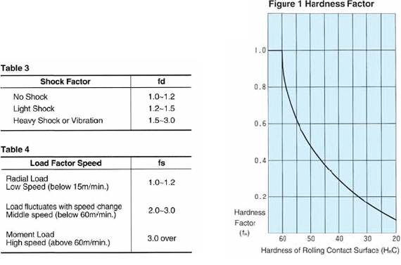
The dynamic load rating C of a ball bush is based on the condition that the hardness of the shaft is over HRC58. When the hardness of the shaft is less than that value, the service life is shortened and the load capacity is reduced. In such a case, the rating life must be multiplied by the hardness factor (ft) shown in Figure 1.
●ft Temperature Factor
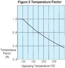
When the operating temperature is in excess of 100℃, the hardness of the rolling contact surface decreases, at the same time the service life and the load capacity is reduced as well. Therefore it is necessary to multiply the rating life by the temperature factor (ft) shown in Figure 2.
* Please note that the max. operating temperature for the ball bushes with plastic retainer is 80℃.
●fd shock Factor
Permanent deformation caused by vibration or shock load under stationary or running conditions of a ball bush may shorten the service life. Therefore the service life must be multiplied by the shock factor (fd) shown in Table 3.
●fs Load Factor
The dynamic load rating of a ball bush is based on the condition that the load are distributed evenly on one ball track. If the load is subject to centralize to a certain point of the ball track due to moment load or extreme deflection of the shaft, the rating life must be multiplied by the load factor (fs) shown in Table 4.
●fq Factor for position of ball circuits
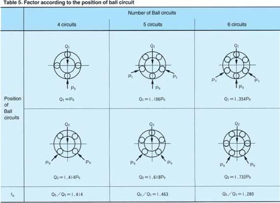
The load rating of a ball bush varies with the position of ball circuits relative to the direction of loading. As shown in Table 5, the load rating varies, depending on whether the load acts on one ball circuit or on the center line between two ball circuits. The load rating is greater in applications where the load acts on the center line of two ball circuits (under the condition of zero radial clearance).
Therefore it is necessary to multiply the rating life by the factor fq shown in Table 5 according to the position of ball circuits 16 ASK
Example of Calculation of Effective Load
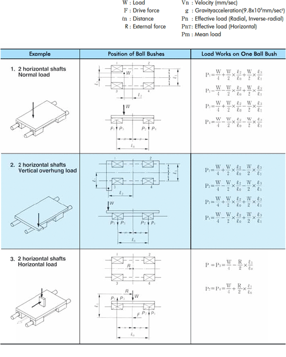
The load which works on a ball bush mounted to a machine installation varies by the position of gravity, the location of drive force and so on, or with the change of speed (acceleration/deceleration) at the moment of start or stop etc. It is necessary to calculate the effective load in consideration of these conditions. The following are examples of calculation of effective load in 7 typical patterns of application:
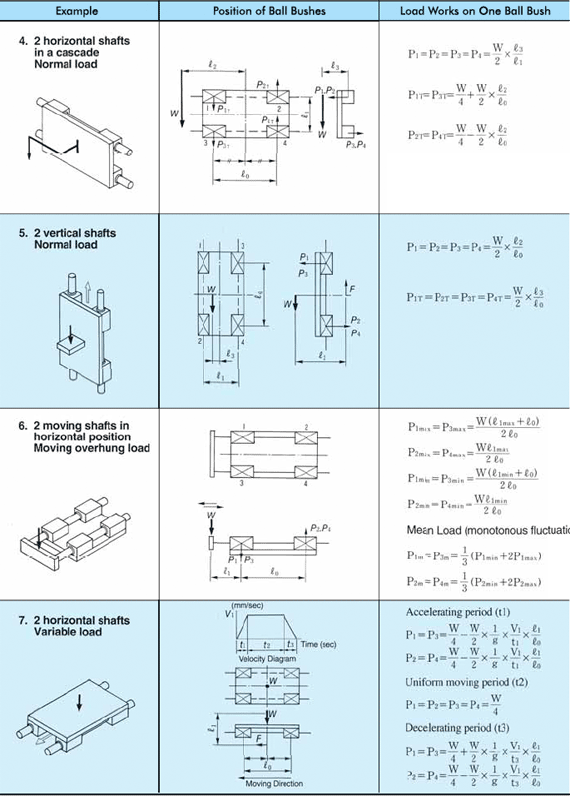
Calculation of Mean Effective Load Under Variable Loading Conditions
When the load working on a ball bush fluctuates under various conditions during operation, the service life can be calculated by finding the mean load. Examples of the calculation of the mean load for some typical patterns of fluctuation are shown as follows:
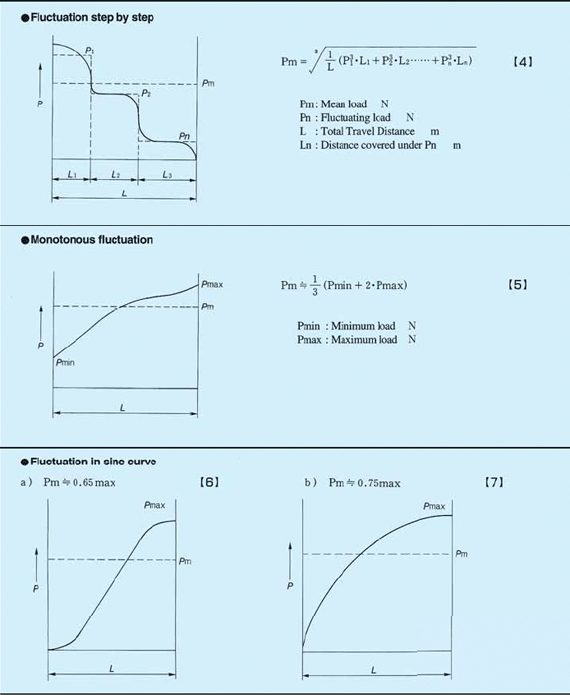
Example of Calculation of Mean Effective Load
In case of vertical transportation of the work, where the effective load on the table at ascent changes from that at descent.

In the above application, a load(W1) is lifted to the top of the vertical stroke. At the top of the stroke the load is removed and the system returns under its own weight(W2). We can find the effective loads for each moment of ascent and descent by following the formula for example 5 on page 15.

Because the load fluctuates step by step as shown in the figure below, the mean load can be calculated by using the formula【4】in page 16.

FRICTION AND LUBRICATION
Rolling Friction

One of the major advantages of ball bushes is that its frictional loss is very small because it makes rolling contact on the shaft. Especially its starting friction is much smaller than that of the slid bearing.
So the machine using ball bushes can be started with considerably smaller power. Generally speaking, the small frictional loss means that the efficiency of the machine is high, and that the machine can be operated with very small power.
Consequently the operating and manufacturing costs of the machine can be reduced. Generation of heat during operation is also small so seizure of the machine does not occur.
Factors Affecting Friction

The factors which affect the friction of ball bushes are operating speed, load, kind and quantity of lubricants, roughness of the shaft surface , etc.
The figure on the right shows an example how the operating speed influences the friction factor of a ball bush. As it is shown here, such influence is usually very small and it produces practically no change in the friction factor.
The kind and quantity of lubricants also affects the friction. When high viscosity oil is used in large quantities, the friction factor increases considerably. Therefore, please use the oil of proper viscosity in the proper quantities according to the given operating conditions of the bushes.
The rolling friction resistance of a ball bush can be calculated by the following formula:

INSTALLATION
Standard Ball Bushes, Closed type
As shown in the following figures, ASK standard Ball Bushes (closed type) can be fitted by stop rings.

Standard Ball Bushes, open type
Fixing plates or anyother proper parts are needed to prevent rolling and axial motion of the ball bush.

SEALING
Ingression of dust in a ball bush can be an obstacle to the rolling motion of the balls. For that reason, a sealing method suitable to your application must be chosen.
●Sealed Type Ball Bushes(with UU at the end)
In order to ensure the best performance of ball bushes, it is necessary to prevent ingression of dust, water, chemical products, etc. from the outside.
Sealed Type are available with rubber seals at one end (with U at the end) or both ends (with UU at the end). Seals wipe out the dust by making contact with the shaft and they also serve to hold the lubricant. The material and design of seals are developed to suit linear motion of ball bushes, so that a higher seal effect can be obtained.
●Felt Ring
In a toxic gas atmosphere where the use of rubber seals is impossible, felt ring type seals are available. A felt type seal is covered with a metal ring, and can be mounted easily to the housing. Please consider the width of the felt ring (column W in the following table), when you design a housing.

